Содержание
Hall-effect thruster — Wikipedia
6 kW Hall thruster in operation at the NASAJet Propulsion Laboratory
In spacecraft propulsion, a Hall-effect thruster (HET) is a type of ion thruster in which the propellant is accelerated by an electric field. Hall-effect thrusters (based on the discovery by Edwin Hall) are sometimes referred to as Hall thrusters or Hall-current thrusters. Hall-effect thrusters use a magnetic field to limit the electrons’ axial motion and then use them to ionize propellant, efficiently accelerate the ions to produce thrust, and neutralize the ions in the plume. The Hall-effect thruster is classed as a moderate specific impulse (1,600 s) space propulsion technology and has benefited from considerable theoretical and experimental research since the 1960s.[1]
Hall thrusters operate on a variety of propellants, the most common being xenon and krypton. Other propellants of interest include argon, bismuth, iodine, magnesium, zinc and adamantane.
Hall thrusters are able to accelerate their exhaust to speeds between 10 and 80 km/s (1,000–8,000 s specific impulse), with most models operating between 15 and 30 km/s. The thrust produced depends on the power level. Devices operating at 1.35 kW produce about 83 mN of thrust. High-power models have demonstrated up to 5.4 N in the laboratory.[2] Power levels up to 100 kW have been demonstrated for xenon Hall thrusters.
As of 2009, Hall-effect thrusters ranged in input power levels from 1.35 to 10 kilowatts and had exhaust velocities of 10–50 kilometers per second, with thrust of 40–600 millinewtons and efficiency in the range of 45–60 percent.[3]
The applications of Hall-effect thrusters include control of the orientation and position of orbiting satellites and use as a main propulsion engine for medium-size robotic space vehicles.[3]
Contents
- 1 History
- 2 Principle of operation
- 2.1 Propellants
- 2.
 1.1 Xenon
 - 2.1.2 Krypton
- 2.
- 2.2 Variants
- 2.2.1 Cylindrical Hall thrusters
- 2.2.2 External discharge Hall thruster
- 2.1 Propellants
- 3 Applications
- 4 In development
- 5 References
- 6 External links
History[edit]
Hall thrusters were studied independently in the United States and the Soviet Union. They were first described publicly in the US in the early 1960s.[4][5][6] However, the Hall thruster was first developed into an efficient propulsion device in the Soviet Union. In the US, scientists focused on developing gridded ion thrusters.
Two types of Hall thrusters were developed in the Soviet Union:
- thrusters with wide acceleration zone, SPT (Russian: СПД, стационарный плазменный двигатель; English: SPT, Stationary Plasma Thruster) at Design Bureau Fakel
- thrusters with narrow acceleration zone, DAS (Russian: ДАС, двигатель с анодным слоем; English: TAL, Thruster with Anode Layer), at the Central Research Institute for Machine Building (TsNIIMASH).

Soviet and Russian SPT thrusters
The SPT design was largely the work of A. I. Morozov.[7][8] The first SPT to operate in space, an SPT-50 aboard a Soviet Meteor spacecraft, was launched December 1971. They were mainly used for satellite stabilization in north–south and in east–west directions. Since then until the late 1990s 118 SPT engines completed their mission and some 50 continued to be operated. Thrust of the first generation of SPT engines, SPT-50 and SPT-60 was 20 and 30 mN respectively. In 1982, the SPT-70 and SPT-100 were introduced, their thrusts being 40 and 83 mN, respectively. In the post-Soviet Russia high-power (a few kilowatts) SPT-140, SPT-160, SPT-200, T-160 and low-power (less than 500 W) SPT-35 were introduced.[9]
Soviet and Russian TAL-type thrusters include the D-38, D-55, D-80, and D-100.[9]
Soviet-built thrusters were introduced to the West in 1992 after a team of electric propulsion specialists from NASA’s Jet Propulsion Laboratory, Glenn Research Center, and the Air Force Research Laboratory, under the support of the Ballistic Missile Defense Organization, visited Russian laboratories and experimentally evaluated the SPT-100 (i. e., a 100 mm diameter SPT thruster). Over 200 Hall thrusters have been flown on Soviet/Russian satellites in the past thirty years.[timeframe?] No failures have ever occurred on orbit. Hall thrusters continue to be used on Russian spacecraft and have also flown on European and American spacecraft. Space Systems/Loral, an American commercial satellite manufacturer, now flies Fakel SPT-100’s on their GEO communications spacecraft.
Since their introduction to the West in the early 1990s, Hall thrusters have been the subject of a large number of research efforts throughout the United States, France, Italy, Japan, and Russia (with many smaller efforts scattered in various countries across the globe). Hall thruster research in the US is conducted at several government laboratories, universities and private companies. Government and government funded centers include NASA’s Jet Propulsion Laboratory, NASA’s Glenn Research Center, the Air Force Research Laboratory (Edwards AFB, California), and The Aerospace Corporation. Universities include the US Air Force Institute of Technology,[10]University of Michigan, Stanford University, The Massachusetts Institute of Technology, Princeton University, Michigan Technological University, and Georgia Tech. A considerable amount of development is being conducted in industry, such as IHI Corporation in Japan, Aerojet and Busek in the US, SNECMA in France, LAJP in Ukraine, SITAEL in Italy, and Satrec Initiative in South Korea.
The first use of Hall thrusters on lunar orbit was the European Space Agency (ESA) lunar mission SMART-1 in 2003.
Hall thrusters were first demonstrated on a western satellite on the Naval Research Laboratory (NRL) STEX spacecraft, which flew the Russian D-55. The first American Hall thruster to fly in space was the Busek BHT-200 on TacSat-2 technology demonstration spacecraft. The first flight of an American Hall thruster on an operational mission, was the Aerojet BPT-4000, which launched August 2010 on the military Advanced Extremely High Frequency GEO communications satellite. At 4.5 kW, the BPT-4000 is also the highest power Hall thruster ever flown in space. Besides the usual stationkeeping tasks, the BPT-4000 is also providing orbit-raising capability to the spacecraft. The X-37B has been used as a testbed for the Hall thruster for the AEHF satellite series.[11] Several countries worldwide continue efforts to qualify Hall thruster technology for commercial uses. The SpaceX Starlink constellation, the largest satellite constellation in the world, uses Hall thrusters. They are also included in the design of the Psyche spacecraft for asteroid exploration.
Principle of operation[edit]
The essential working principle of the Hall thruster is that it uses an electrostatic potential to accelerate ions up to high speeds. In a Hall thruster, the attractive negative charge is provided by an electron plasma at the open end of the thruster instead of a grid. A radial magnetic field of about 100–300 G (10–30 mT) is used to confine the electrons, where the combination of the radial magnetic field and axial electric field cause the electrons to drift in azimuth thus forming the Hall current from which the device gets its name.
Hall thruster. Hall thrusters are largely axially symmetric. This is a cross-section containing that axis.
A schematic of a Hall thruster is shown in the adjacent image. An electric potential of between 150 and 800 volts is applied between the anode and cathode.
The central spike forms one pole of an electromagnet and is surrounded by an annular space, and around that is the other pole of the electromagnet, with a radial magnetic field in between.
The propellant, such as xenon gas, is fed through the anode, which has numerous small holes in it to act as a gas distributor. As the neutral xenon atoms diffuse into the channel of the thruster, they are ionized by collisions with circulating high-energy electrons (typically 10–40 eV, or about 10% of the discharge voltage). Most of the xenon atoms are ionized to a net charge of +1, but a noticeable fraction (c. 20%) have +2 net charge.
The xenon ions are then accelerated by the electric field between the anode and the cathode.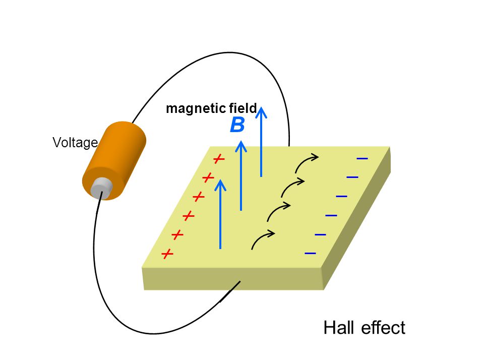 For discharge voltages of 300 V, the ions reach speeds of around 15 km/s (9.3 mi/s) for a specific impulse of 1,500 s (15 kN·s/kg). Upon exiting, however, the ions pull an equal number of electrons with them, creating a plasma plume with no net charge.
The radial magnetic field is designed to be strong enough to substantially deflect the low-mass electrons, but not the high-mass ions, which have a much larger gyroradius and are hardly impeded. The majority of electrons are thus stuck orbiting in the region of high radial magnetic field near the thruster exit plane, trapped in E×B (axial electric field and radial magnetic field). This orbital rotation of the electrons is a circulating Hall current, and it is from this that the Hall thruster gets its name. Collisions with other particles and walls, as well as plasma instabilities, allow some of the electrons to be freed from the magnetic field, and they drift towards the anode.
About 20–30% of the discharge current is an electron current, which does not produce thrust, thus limiting the energetic efficiency of the thruster; the other 70–80% of the current is in the ions. Because the majority of electrons are trapped in the Hall current, they have a long residence time inside the thruster and are able to ionize almost all of the xenon propellant, allowing mass use of 90–99%. The mass use efficiency of the thruster is thus around 90%, while the discharge current efficiency is around 70%, for a combined thruster efficiency of around 63% (= 90% × 70%). Modern Hall thrusters have achieved efficiencies as high as 75% through advanced designs.
Compared to chemical rockets, the thrust is very small, on the order of 83 mN for a typical thruster operating at 300 V and 1.5 kW. For comparison, the weight of a coin like the U.S. quarter or a 20-cent euro coin is approximately 60 mN. As with all forms of electrically powered spacecraft propulsion, thrust is limited by available power, efficiency, and specific impulse.
However, Hall thrusters operate at the high specific impulses that are typical for electric propulsion. One particular advantage of Hall thrusters, as compared to a gridded ion thruster, is that the generation and acceleration of the ions takes place in a quasi-neutral plasma, so there is no Child-Langmuir charge (space charge) saturated current limitation on the thrust density. This allows much smaller thrusters compared to gridded ion thrusters.
Another advantage is that these thrusters can use a wider variety of propellants supplied to the anode, even oxygen, although something easily ionized is needed at the cathode.[12]
Propellants[edit]
Xenon[edit]
Xenon has been the typical choice of propellant for many electric propulsion systems, including Hall thrusters.[13] Xenon propellant is used because of its high atomic weight and low ionization potential. Xenon is relatively easy to store, and as a gas at spacecraft operating temperatures does not need to be vaporized before usage, unlike metallic propellants such as bismuth. Xenon’s high atomic weight means that the ratio of energy expended for ionization per mass unit is low, leading to a more efficient thruster.[14]
Krypton[edit]
Krypton is another choice of propellant for Hall thrusters. Xenon has an ionization potential of 12.1298 eV, while krypton has an ionization potential of 13. 996 eV.[15] This means that thrusters utilizing krypton need to expend a slightly higher energy per mole to ionize, which reduces efficiency. Additionally, krypton is a lighter ion, so the unit mass per ionization energy is further reduced compared to xenon. However, xenon can be more than ten times as expensive as krypton per kilogram, making krypton a more economical choice for building out satellite constellations like that of SpaceX’s Starlink, whose Hall thrusters are fueled with krypton.[16][17]
Variants[edit]
Cylindrical Hall thrusters[edit]
An Exotrail ExoMG – nano (60 W) Hall Effect Thruster firing in a vacuum chamber
Although conventional (annular) Hall thrusters are efficient in the kilowatt power regime, they become inefficient when scaled to small sizes. This is due to the difficulties associated with holding the performance scaling parameters constant while decreasing the channel size and increasing the applied magnetic field strength.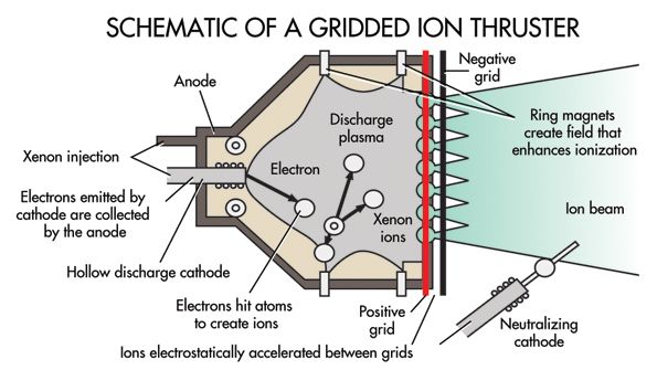 This led to the design of the cylindrical Hall thruster. The cylindrical Hall thruster can be more readily scaled to smaller sizes due to its nonconventional discharge-chamber geometry and associated magnetic field profile.[18][19][20] The cylindrical Hall thruster more readily lends itself to miniaturization and low-power operation than a conventional (annular) Hall thruster. The primary reason for cylindrical Hall thrusters is that it is difficult to achieve a regular Hall thruster that operates over a broad envelope from c.1 kW down to c. 100 W while maintaining an efficiency of 45–55%.[21]
External discharge Hall thruster[edit]
Sputtering erosion of discharge channel walls and pole pieces that protect the magnetic circuit causes failure of thruster operation. Therefore, annular and cylindrical Hall thrusters have limited lifetime. Although magnetic shielding has been shown to dramatically reduce discharge channel wall erosion, pole piece erosion is still a concern.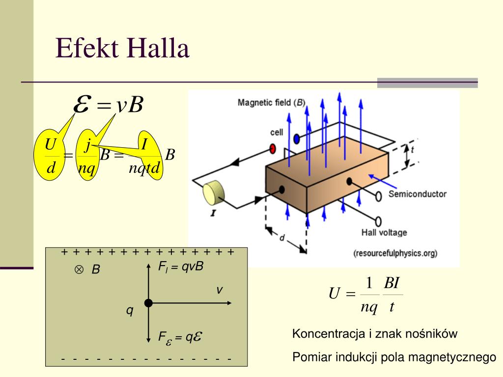 [22] As an alternative, an unconventional Hall thruster design called external discharge Hall thruster or external discharge plasma thruster (XPT) has been introduced.[23][24][25] The external discharge Hall thruster does not possess any discharge channel walls or pole pieces. Plasma discharge is produced and sustained completely in the open space outside the thruster structure, and thus erosion-free operation is achieved.
Applications[edit]
An illustration of the Gateway in orbit around the Moon. The orbit of the Gateway will be maintained with Hall thrusters.
Hall thrusters have been flying in space since December 1971, when the Soviet Union launched an SPT-50 on a Meteor satellite.[26] Over 240 thrusters have flown in space since that time, with a 100% success rate.[27] Hall thrusters are now routinely flown on commercial LEO and GEO communications satellites, where they are used for orbital insertion and stationkeeping.
The first[failed verification] Hall thruster to fly on a western satellite was a Russian D-55 built by TsNIIMASH, on the NRO’s STEX spacecraft, launched on October 3, 1998.[28]
The solar electric propulsion system of the European Space Agency’s SMART-1 spacecraft used a Snecma PPS-1350-G Hall thruster.[29] SMART-1 was a technology demonstration mission that orbited the Moon. This use of the PPS-1350-G, starting on September 28, 2003, was the first use of a Hall thruster outside geosynchronous earth orbit (GEO). Like most Hall thruster propulsion systems used in commercial applications, the Hall thruster on SMART-1 could be throttled over a range of power, specific impulse, and thrust.[30] It has a discharge power range of 0.46–1.19 kW, a specific impulse of 1,100–1,600 s and thrust of 30–70 mN.
Many small satellites of the SpaceX Starlink cluster use krypton-fueled Hall thrusters for position-keeping and deorbiting. [17]
[17]
Tiangong space station is fitted with Hall-effect thrusters. Tianhe core module is propelled by both chemical thrusters and four ion thrusters,[31] which are used to adjust and maintain the station’s orbit. The development of the Hall-effect thrusters is considered a sensitive topic in China, with scientists «working to improve the technology without attracting attention».[citation needed] Hall-effect thrusters are created with crewed mission safety in mind with effort to prevent erosion and damage caused by the accelerated ion particles. A magnetic field and specially designed ceramic shield was created to repel damaging particles and maintain integrity of the thrusters. According to the Chinese Academy of Sciences, the ion drive used on Tiangong has burned continuously for 8,240 hours without a glitch, indicating their suitability for the Chinese space station’s designated 15-year lifespan.[32] This is the world’s first Hall thruster on a human-rated mission. [33]
[33]
The Jet Propulsion Laboratory (JPL) granted exclusive commercial licensing to Apollo Fusion, led by Mike Cassidy, for its Magnetically Shielded Miniature (MaSMi) Hall thruster technology.[34] In January 2021, Apollo Fusion announced they had secured a contract with York Space Systems for an order of its latest iteration named the «Apollo Constellation Engine».[35]
The NASA mission to the asteroid Psyche will utilize xenon gas Hall thrusters.[36] The electricity will come from the craft’s 75 square meter solar panels.[37]
NASA’s first Hall thrusters on a human-rated mission will be a combination of 6 kW Hall thrusters provided by Busek and NASA Advanced Electric Propulsion System (AEPS) Hall thrusters. They will serve as the primary propulsion on Maxar’s Power and Propulsion Element (PPE) for the Lunar Gateway under NASA’s Artemis program.[38] The high specific impulse of Hall thrusters will allow for efficient orbit raising and station keep for the Lunar Gateway’s polar near-rectilinear halo orbit.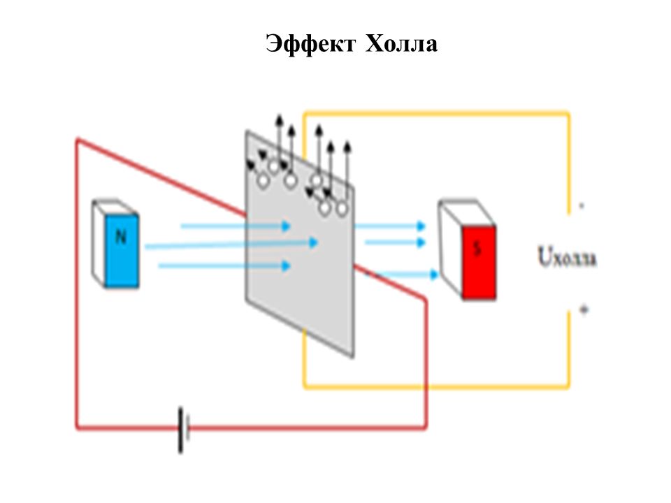 Daniel A. Herman, Todd A. Tofil, Walter Santiago, Hani Kamhawi, James E. Polk, John S. Snyder, Richard R. Hofer, Frank Q. Picha, Jerry Jackson and May Allen. «Overview of the Development and Mission Application of the Advanced Electric Propulsion System (AEPS)» (PDF). NASA; NASA/TM–2018-219761. 35th International Electric Propulsion Conference. Atlanta, Georgia, October 8–12, 2017. Retrieved 27 July 2018.
External links[edit]
- Edgar, Y. (2009). New Dawn for Electric Rockets
- SITAEL S.p.A. (Italy)—Page presenting Hall effect thruster products & data sheets
- Snecma SA (France) page on PPS-1350 Hall thruster
- Electric Propulsion Sub-Systems (PDF)
- Stationary plasma thrusters Archived 2019-07-11 at the Wayback Machine (PDF)
- ESA page on Hall thrusters
- Apollo Fusion
- «How the Hall Effect Still Reverberates». IEEE Spectrum. 2022-01-28.
Холловский двигатель (двигатель на основе эффекта Холла)
Производство двигателей и турбин Производство машин и оборудования Прорывные технологии
Холловский двигатель (двигатель на основе эффекта Холла).
Холловский двигатель (двигатель на основе эффекта Холла) является одной из разновидностей электростатического ракетного двигателя. Он позволяет получить более высокую плотность тяги, более высокие значения расхода рабочего тела, и, как следствие, более высокую тягу двигателя, чем ионный двигатель.
Устройство и принцип работы холловского двигателя
Схема холловского двигателя
Отличия и преимущества холловского двигателя по сравнению с ионным
Примерные технические характеристики холловского двигателя
Устройство и принцип работы холловского двигателя:
Холловский двигатель (двигатель на основе эффекта Холла) – это одна разновидностей электростатического ракетного двигателя, в котором используется эффект Холла. Двигатели на основе эффекта Холла используются на космических аппаратах с 1972 года.
В основе принципа работы данного двигателя лежит эффект Холла, открытый в 1879 г. Эдвином Холлом (Edwin H. Hall). Он заключается в том, что в проводнике, в котором созданы взаимно перпендикулярные электрическое и магнитное поля, возникает электрический ток (называемый холловским) в направлении, перпендикулярном обоим этим полям. Иными словами, если электрическое и магнитное поля имеют направления соответственно по осям X и Y, то электрический (холловский) ток имеет направление вдоль оси Z.
Холловский двигатель состоит из кольцевой камеры. Иными словами, камера двигателя выполнена в форме кольца (цилиндра). С одной стороны в камеру подаётся рабочее тело, с другой стороны происходит истекание плазмы. Внутри двигателя располагается анод (положительный электрод), катод (отрицательный электрод) расположен снаружи двигателя. По внешней стороне кольца располагаются магниты.
Между анодом и катодом создается разность потенциалов. В кольцевую камеру подаётся рабочее тело (например, ксенон). Разряд между анодом и катодом ионизирует рабочее тело, отрывая электроны от нейтральных атомов газа. Под действием электростатического поля положительные ионы газа (плазма) разгоняются в осевом направлении – в направлении выходного отверстия цилиндрического двигателя. На выходе из двигателя происходит нейтрализация положительного заряда плазмы электронами, эмитируемыми с катода. Истечение положительных ионов из выходного отверстия создает тягу.
В радиальном направлении действует магнитная сила, которая в соответствии с эффектом Холла приводит к появлению электрического тока, движущегося в азимутальном направлении (т.е. вокруг центрального электрода, оси двигателя). Холловский ток создается движением электронов в электрическом и магнитном полях.
В холловском двигателе тяга создается также с помощью холловского тока, пересекающего радиальное магнитное поле. Их взаимодействие заставляет электроны обращаться вокруг оси двигателя. Эти электроны выбивают электроны из атомов ксенона, создавая ионы ксенона, которые осевое электрическое поле ускоряет в направлении выходного отверстия двигателя. Электроны холловского тока под действием силы Лоренца (возникающей в результате взаимодействия приложенного радиального магнитного поля с электрическим холловским током) создают дополнительную тягу и вырываются наружу в выходное отверстие вместе с положительными ионами.
Двигатель на основе эффекта Холла позволяет получить более высокую плотность тяги, более высокие значения расхода рабочего тела, и, как следствие, более высокую тягу двигателя, чем ионный двигатель, поскольку в истекающем потоке содержатся и положительные ионы, и электроны, что предотвращает накопление объемного заряда, уменьшающего напряженность ускоряющего электрического поля.
В зависимости от располагаемой мощности скорости истечения рабочего тела могут составлять от 10 до 50 км/с.
Схема холловского двигателя:
Рис. 1. Устройство холловского двигателя
http://go2starss.narod.ru/pub/E025_ID.html
Отличия и преимущества холловского двигателя по сравнению с ионным:
– двигатель на основе эффекта Холла при равных размерах имеет большую тягу, чем ионный, поэтому способен разгонять космический аппарат до высоких скоростей быстрее, чем ионный двигатель сравнимого размера.
Примерные технические характеристики холловского двигателя:
| Характеристики: | Значение: |
| Потребляемая мощность, кВт | 1,35-10 |
| Скорость истечения ионов, км/с | 10-50 |
| Тяга, мН | 40-600 |
| КПД, % | 45-60 |
| Время непрерывной работы, лет | более 3 |
Источник: http://cyclowiki.org/wiki/Холловский_двигатель, http://go2starss.narod.ru/pub/E025_ID.html
© Фото https://www.pexels.com, https://pixabay.com, http://go2starss.narod.ru/pub/E025_ID.html
Коэффициент востребованности
1 654
Датчик Холла и его роль в контроллере двигателя
Датчик Холла — это широко используемый датчик, обеспечивающий обратную связь о положении ротора с контроллером двигателя. Давайте разберемся со значением этого датчика в системе управления автомобильным двигателем.
A Система управления двигателем BLDC представляет собой сложную схему, в которой несколько компонентов работают в тандеме, чтобы заставить двигатель двигаться желаемым образом. Эффективность, долговечность и производительность — это атрибуты, которые больше всего беспокоят инженеров при разработке такой системы.
В то время как магниты и катушки заботятся об электрическом аспекте, микроконтроллер действует как мозг, приводящий в движение двигатель. Но даже самый острый мозг нуждается в сенсорной информации.
Здесь большое значение имеют два сенсорных входа: Скорость и Положение . Давайте разберемся с ними в контексте коммутации двигателя.
Коммутация — это процесс переключения тока в фазах двигателя для облегчения вращения двигателя.
В коллекторных двигателях щетки контактируют с коллектором и переключают ток для движения двигателей. Двигатели BLDC не имеют щеток; таким образом, они должны приводиться в движение электронным способом с помощью системы управления двигателем.
Контроллер двигателя BLDC подает прямоугольные сигналы (напряжение) на магниты ротора и создает магнитное поле, которое приводит в движение двигатель.
Значение скорости и положения ротора при коммутации двигателя:
Коммутация в BLDC двигателе представляет собой 6-шаговый процесс . Трехфазный Н-мост используется для создания 6 векторов потока , каждый из которых вызывает поворот двигателя на 60 градусов (соответствует следующему положению), таким образом совершая полный оборот на 360 градусов.
- Чтобы двигатель двигался, контроллер двигателя подает ток через катушку статора. Это создает магнитное поле, которое, в свою очередь, создает крутящий момент на роторе (постоянный магнит). В результате ротор начинает двигаться.
- Теперь, если ротор приблизится к движущему его магнитному полю, ротор будет стремиться остановиться из-за изменения полярности. В этот момент магнитное поле начнет притягивать ротор и остановит движение.
 Чтобы этого избежать, система управления двигателем переключает ток, подаваемый на статор, и создается новое магнитное поле, а ротор продолжает свое движение. Таким образом, процесс коммутации сводится к переключению тока в правильном экземпляре .
 - Понятие скорости и положения появляется на картинке, поскольку этот «правильный экземпляр» должен ощущаться, когда он прибывает.
- Датчик необходим для обратной связи с системой управления двигателем, указывающей, когда ротор достиг нужного положения. Если коммутация выполняется быстрее или медленнее, чем скорость ротора, магниты выходят из синхронизации с магнитным полем статора. Это заставляет ротор вибрировать и останавливаться вместо того, чтобы вращаться.
- После одной коммутации необходимо определить положение ротора относительно статора, чтобы можно было инициировать следующую коммутацию. И, следовательно, определение положения также является важным параметром.
Существует много типов датчиков, используемых в производстве электродвигателей, таких как энкодеры, переключатели и потенциометры. Однако наиболее широко используемым и развернутым датчиком является датчик Холла .
В следующих разделах мы подробно поговорим о датчике Холла и его роли в системе управления двигателем.
Что такое датчик Холла?
Датчик на эффекте Холла представляет собой преобразователь, основанный на принципе эффекта Холла.
Эффект получения измеряемого напряжения, когда проводник или полупроводник с током, текущим в одном направлении, вводится перпендикулярно магнитному полю, называется эффектом Холла.
Проще говоря, напряжение возникает на электрическом проводнике, когда к нему прикладывается магнитное поле в направлении, перпендикулярном протеканию тока.
Датчик на эффекте Холла представляет собой полупроводниковое устройство, использующее этот принцип для определения положения, скорости и различных других характеристик, необходимых для эффективной работы двигателя BLDC.
Увеличенный вид датчика Холла
Через полосу Холла постоянно протекает небольшой ток.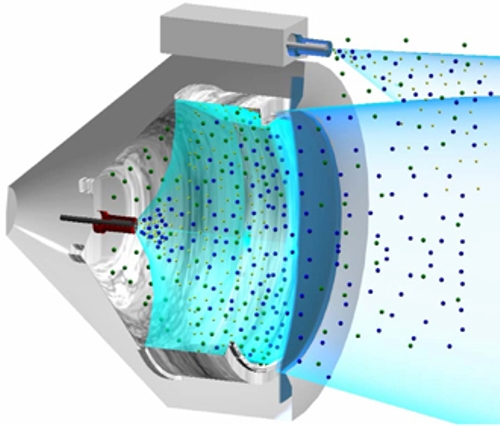 Как уже упоминалось, переменное поле от этого магнита ротора будет создавать напряжение на полосе Холла. Затем напряжение подается на цифровую схему (показана на диаграмме выше), которая, в свою очередь, выдает цифровой сигнал в виде выходного сигнала датчика Холла.
Как работает датчик Холла в двигателе с бесконтактным двигателем постоянного тока
Как правило, двигатель с бесконтактным двигателем имеет три датчика Холла, установленных на роторе или статоре. Эти датчики Холла расположены на расстоянии 120 градусов друг от друга, обеспечивая угловое положение от 0 до 360 градусов.
Когда эти датчики Холла вступают в контакт с магнитным полем ротора, они генерируют соответствующие цифровые импульсы с единицами и 0, как показано на диаграмме ниже.
За шесть шагов эти датчики Холла могут определить положение двигателя (угол). На диаграмме прямоугольные формы сигналов демонстрируют положительный и отрицательный импульсы, генерируемые под соответствующим углом всеми тремя датчиками Холла — A, B и C.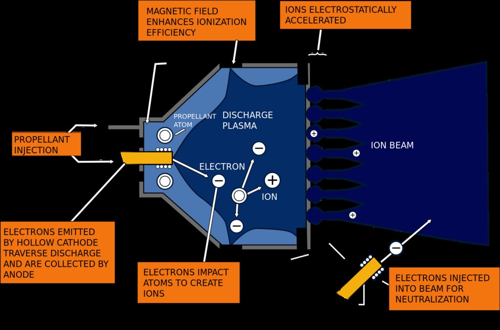
достигла 360 градусов.
Следующее объяснение внесет больше ясности.
Когда магнит ротора пересекает один из датчиков, он генерирует низкий или высокий сигнал в зависимости от того, прошел ли он северный или южный полюс ротора. Когда ротор пересекает все три датчика, эти датчики переключаются между низким и высоким уровнем, таким образом выдавая положение ротора каждые 60 градусов.
На приведенной ниже схеме показан типичный контроллер двигателя BLDC. Три линии, идущие от двигателя к контроллеру, изображают сигнал, посылаемый тремя датчиками Холла.
Датчик Холла способен различать положительный и отрицательный заряды, движущиеся в противоположном направлении. Магнитное поле, обнаруженное датчиком Холла, преобразуется в подходящий аналоговый или цифровой сигнал, который может считываться электронной системой, обычно системой управления двигателем.
Ниже показана таблица истинности, полученная на основе показаний трех датчиков Холла. Как видите, состояние транзистора H-моста зависит от сигнала, обнаруженного датчиком. Стрелка вниз показывает движение по часовой стрелке (CW), а стрелка вверх показывает движение против часовой стрелки (CCW).
Теперь, когда у нас есть таблица истинности и график, можно легко рассчитать угол (положение) и скорость ротора.
Преимущества использования датчика Холла в контроллере двигателя постоянного тока BLDC
- Датчик Холла представляет собой очень простое устройство, состоящее из магнитов, поэтому оно очень экономично для систем управления двигателем.
- По той же причине эти датчики легко внедрить в передовые системы управления двигателем для электромобилей и другие автомобильные решения.
- Большинство двигателей BLDC оснащены этими датчиками.
- в основном невосприимчивы к условиям окружающей среды, таким как влажность, температура, пыль и вибрация.
Датчики Холла
Завершение
Многое происходит внутри системы управления двигателем BLDC.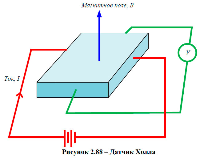 Есть алгоритм FOC, схемы H-Bridge, эффективная коммутация и многое другое. Среди множества компонентов внутри системы управления двигателем BLDC очень маленький и скромный датчик — датчик Холла — дает о себе знать.
Будучи экономичными и простыми в применении, эти датчики сделали современные решения управления двигателями постоянного тока более эффективными и удобными в использовании в автомобильной промышленности.
Посмотрите это место, чтобы узнать о других подобных компонентах, которые играют жизненно важную роль в контроллере двигателя BLDC.
Что такое датчики Холла и какова их роль в двигателях постоянного тока?
Вы здесь: Домашняя страница / Часто задаваемые вопросы + основы / Часто задаваемые вопросы: Что такое датчики Холла и какова их роль в двигателях постоянного тока?
Даниэль Коллинз Оставить комментарий
Двигатели постоянного тока могут быть щеточного типа, которые коммутируются механически, или бесщеточными, которые коммутируются электрически.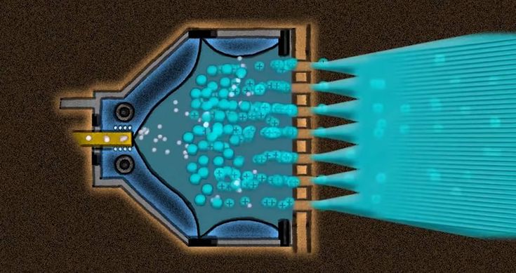 В бесщеточных двигателях постоянного тока (BLDC) датчики Холла используются вместо механического коммутатора и щеток.
Датчики Холла представляют собой полупроводниковые датчики магнитного поля. Они работают по принципу, согласно которому, когда проводник с током, протекающим по нему, помещается в магнитное поле, магнитное поле индуцирует поперечную (или боковую) силу на носителях заряда, которая отталкивает их в стороны от проводника – отрицательная на единицу сторону и положительный на другую сторону. Это накопление заряда на сторонах проводника индуцирует напряжение. Этот эффект называют эффектом Холла в честь его первооткрывателя Эдвина Холла.
Бесщеточный двигатель постоянного тока с тремя датчиками Холла для определения положения ротора.
Изображение предоставлено: Honeywell International Inc.
Целью коммутации, будь то механическими или электрическими средствами, является подача питания на обмотки статора в определенной последовательности, при этом одна обмотка положительная, одна отрицательная, а третья отключена.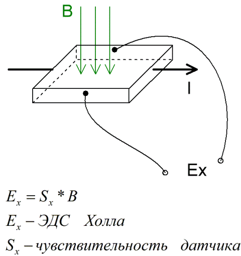 Создание крутящего момента вызвано притяжением и отталкиванием между полем статора и постоянными магнитами ротора. Максимальный крутящий момент достигается, когда эти два поля ориентированы на 90 градусов друг к другу, и крутящий момент уменьшается по мере выравнивания их полей. Следовательно, чтобы двигатель продолжал вращаться, магнитное поле статора должно менять свое положение по мере того, как поле ротора «догоняет» его.
Чтобы подать питание на правильную обмотку статора, необходимо знать положение ротора. Это работа датчиков Холла — следить за положением ротора. Двигатели BLDC обычно имеют три датчика Холла, установленных либо на статоре, либо на роторе, и используют так называемую шестиступенчатую коммутацию. Когда ротор проходит мимо датчика, он выдает либо высокий, либо низкий сигнал, указывающий, какой полюс ротора (N или S) прошел. Это переключение трех датчиков Холла (с высокого на низкий или с низкого на высокий) предоставляет информацию о положении ротора каждые 60 градусов.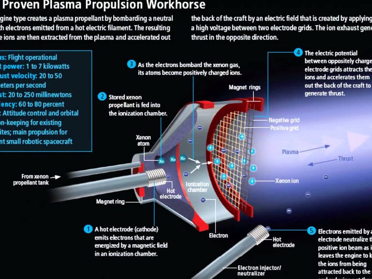

 1.1 Xenon
 Чтобы этого избежать, система управления двигателем переключает ток, подаваемый на статор, и создается новое магнитное поле, а ротор продолжает свое движение. Таким образом, процесс коммутации сводится к переключению тока в правильном экземпляре .